
Improving Machine Tool Linear Accuracy with Laser Scales

Aerospace machine tools are enhancing accuracy with new laser scale and thermal compensation.
By Howard Salt, Renishaw, Inc.
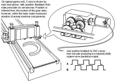
Where does machine tool linear accuracy come from? Many things contribute to it, but the device your machine tool probably uses to measure its linear position is actually rotary in nature—an optical or magnetic encoder or resolver on the servomotor shaft that drives the ballscrew. The CNC effectively associates a certain number of counts from this rotational device with linear positions for the spindle.
This would be fine in a perfect world where screw leads were true and drives were backlash-free. But in the real world, these are inherent sources of linear error that machine tool makers compensate for with laser calibration and special software in the CNC. For axes of about a meter, this works very well until the ballscrews, bearings, rack/pinion, or other components wear a little and get sloppy. A typical 600 mm pallet horizontal machining center with this setup can deliver "new" accuracy of around ±0.0002 in. (±0.005 mm); this can often be halved by going to an expensive, optional linear glass scale.
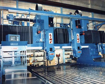
However, in the aerospace industry, machine axes are often longer than a meter, and glass scales, because of cost and physical limitations, are not a practical option for accuracy enhancement (see Figure 1). Thus, the aerospace industry has driven the development of a new laser-based linear position feedback system for large machines. It's complemented by a thermal compensation system that allows large aluminum parts to be measured for temperature, and machined accurately in a non-temperature-controlled environment, too.
This system is yielding accuracy improvements of 20–30X for large machine tools and assembly systems. It brings accuracy down to the repeatability of the machine—check out your machine's specs, and you'll appreciate what this means—about 1 part per million (ppm) (±1 micron per meter) on axes out to 250 ft (75 m), or about ±0.0004 in. for a 40-ft axis.
Because this system measures the true position of a machine component such as a column, it can be retrofitted to existing, older machines and deliver this positional accuracy improvement. A cost-effective version of this same technology is in OEM use on new standard machines, too.
Aerospace Drives the Advance
As with many significant advances in machine tools, the aerospace industry is pushing the accuracy and technology envelope. Why? Because the size, shape, and temperature sensitivity of parts in the aerospace industry make it extremely difficult to achieve print tolerances. Part costs are high, and part runs are so short there is no "trend" to monitor with statistical process control.
If machining variances can be reduced even 0.001 in. on the myriad parts in an airframe, the cumulative effect can be a measurable weight reduction in the final product. Weight variances are a critical concern in the aerospace industry. Boeing's chief engineer for weights said in a PBS documentary on the building of the 777 that the company considers weight variances "a measure of our capability to produce airplanes." To give some idea, the true weight of the very first Boeing 777, which was designed entirely using computer software, was calculated in advance within 36 lbs of its final weight. A very exacting target, considering a gross airplane weight of 297,464 lbs.
More to the point, the PBS documentary stated that "if the [first] plane was heavier than the guaranteed weight, Boeing could have to pay United [Airlines] up to $500 per plane, per year, for every pound overweight, to compensate for the fact they would either have to carry less weight on board or burn more fuel."
But weight alone is not the issue. Aircraft makers are striving to enjoy one of the cost economies that many other makers of machined parts take for granted: automated assembly. Greater adherence to print tolerance reduces the amount of shimming in final assembly. Improved part accuracy also opens the door to greater use of automated assembly machines. The "stacking error" in conventionally machined wing components, for example, currently makes automated wing assembly very difficult.
Two Sources of Error Addressed
Machine inaccuracies tend to come from two sources:
• the axis position measuring system: aerospace machines—often equipped with rack-and-pinion drives, and encoders or traditional scales for position feedback—simply cannot deliver ultra-high accuracies even when new.
• fluctuating environmental conditions cause dimensional changes in the part during the cut.
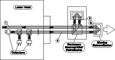
The laser scale and compensation unit address both these problems. The scale is based on technology used for laser calibration of machine tools, widely known as linear error compensation. Theoretical accuracy for a laser calibration system is ±0.1 ppm (±0.025 µm) (±1 µin.). The scale uses the same principle—interferometry (see sidebar)—but packaged for the machining environment. Beam strength, optical sensitivity, and other features have all been enhanced over a calibration laser to achieve high accuracy in an actual machining environment. The scale is shock rated to 35g, tolerates vibration of 10g at 3-300 Hz, and is sealed to IP65 (NEMA 12/13).
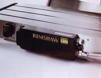
The scale functions as an independent measurement reference, unaffected by backlash in the drive. That is, it measures the actual position of the machine for the CNC. Traditional axis position feedback systems, with optical and magnetic encoders or resolvers on the servomotor shaft driving the ballscrew, can only tell the CNC what the servomotor is doing. It is assumed that the tool point is moving in perfect synchronization with the motor, but this is rarely physically possible. Unlike a glass scale, a laser has no short-term errors which can "stack up" on long axes, and its 2,400 ipm measuring speed accommodates today's fast-moving machine tools.
The laser scale integrates with CNCs capable of reading an A/B quadrature signal (RS-485 port), which is the standard signal produced by linear and rotary encoders. Only the laser source and two small optical elements mount on the machine. Protection from the machining environment can range from nothing to minimal shielding with simple sheet metal covers. Simple plastic pipe has also been used as protection.
Temperature Compensation
A large, asymmetrical workpiece of thermally responsive aluminum is literally a moving target during the machining process. Spars and other aluminum parts can change length by 0.1 in. or more in a few hours, responding to changes in plant environment.
This behavior is predictable, however, and can be mapped in CATIA or other CAD/CAM systems. The thermal compensation unit, linked between the scale and the CNC, uses that prediction, along with input from temperature, pressure, and humidity sensors, to adjust the laser scale's signal (see Figure 2). The temperature of the machine, part, and air are all accounted for. The latter is needed, along with humidity and pressure, to compensate for the refractive index of air that affects the laser beam.
The compensation unit is an industrial, Pentium-based, rack PC. It can compensate up to six axes, with inputs for both a scale and reference mark switches on each axis. PC architecture permits continuous upgrades.
Compensation can be dynamic, for thermally sensitive materials that are known to change and expand during machining or simply "frozen," for large, thermally stable workpieces that are well fixtured on vacuum tables.
The unit can apply a simple textbook coefficient of expansion for a workpiece and adjust all axes with the same factor. Or, much more can be done to achieve the highest accuracies on thermally sensitive, asymmetrical parts, such as a wedge shape, where expansion and contraction rates vary dramatically from one area of a part to another. The variation can be further complicated by the way the part is fixtured. However, a programmer can see this behavior as the part model is "heated" in CAD/CAM software.
Using model information, aerospace CNC programmers have been able to:
• calculate a new, arbitrary coefficient of expansion that reflects more accurately the true behavior of the part
• calculate multiple coefficients of expansion that account for the different directions of part expansion/contraction in relation to fixturing points and reference mark signals
• create bounded temperature zones on the part with site-specific compensation data
In fact, a creative programmer can virtually linearize the expansion behavior of highly asymmetrical parts, such as those with varying thicknesses, shapes, holes, pockets, honeycombs, laminations, etc.—any part that can be modeled in CAD/CAM software.
Not Just for Aerospace
The technology needed to satisfy the demands of aerospace machining ultimately migrates to all machine tools, much as servo control and NC did. That migration will occur much faster for laser scales and improved thermal compensation. A cost-effective system for standard machines is in development now. And unlike NC and servo control, the laser scale won't be limited to new machines alone. It can be easily retrofitted to old machines to give them accuracy that will be nearly equal to the best new machines.
Born and educated in Scotland, Howard Salt originally worked for Rolls Royce Aerospace division in Derby, England, before moving to LK, a leading manufacturer of coordinate metrology equipment. He has been with Renishaw for 10 years, starting as sales and marketing manager for the Encoder and Calibration Business in the U.K. For the last six years, he has been business manager for the Calibration and Encoder Products Division in the U.S.
For more information, contact Renishaw Inc., 623 Cooper Ct., Schaumburg, IL 60173. Tel: 847-843-3666; Fax: 847-843-1744.